Assembly Manual • Schematic • Parts List • Tubes and Applications • Theory of Operation
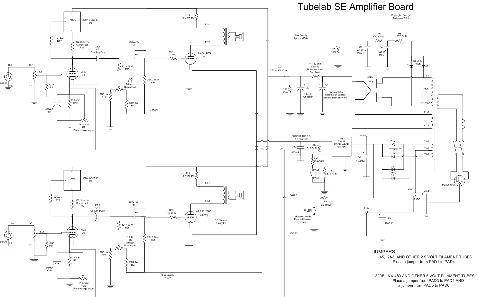
This is the schematic for the Tubelab SE amplifier (TSE).
Assembly Manual • Schematic • Parts List • Tubes and Applications • Theory of Operation
This is the schematic for the Tubelab SE amplifier (TSE).