The MiniTron amplifier was designed for entry into the Circuit Cellar / Microchip design contest. In a sea of microprocessor powered IC based gizmos this vacuum tube amplifier WON ONE OF THE CATEGORY PRIZES!!! It should be featured in the Circuit Cellar magazine, and on their web site in the near future. One component of the MiniTron design is the cathode follower amplifier, which is presented here. This will evolve into a two stand alone SE designs and one P-P design in the coming months. They can be used alone, or as part of the MicroTron, MiniTron, and MegaTron ( a push pull version that is capable of insane power ) amplifier systems.
The contest had some specific rules that had to be met. One of them was complete anonymity. The judges could not know who was submitting what. This led to the "I am up to something but I can't say what" stuff I posted earlier. I will post the entire design on the MiniTron pages as soon as I can get them formatted. New developments will be here and on the MiniTron, MicroTron and MegaTron pages. The complete project that was submitted to the contest is now posted on their web site. There will be one or two articles in their print magazine in the coming year. The project submission can be seen here:
http://www.circuitcellar.com/microchip2007/winners/MT2209.html
This is the SE power amp that started it all. Again this was all the result of the thinking that occurred after someone posted a simple question on the diyAudio forums. See the following threads:
The augmented cathode follower thread led me to discover the work of James Ross Macdonald (after the MiniTron was developed). See http://www.jrossmacdonald.com/ He is still publishing papers in the physics field. He wrote papers about cathode followers and other amplifier designs in the mid 1950's. He wrote about many of the principles used in the MiniTron design in 1957. He even explained the technique of varying the supply voltage with the audio signal but no design was documented. His cathode follower work seems geared toward high impedance low capacitance input stages. I became convinced that they could be used to create the "perfect output stage" so I am currently experimenting along those lines. There are a few patents applied for in 1954 which are now expired. I will post them here in the future. The IRE (now IEEE) papers are still covered by copyright and can not be posted. They can be obtained from the IEEE for a fee. Future developments will be posted.
Original CF Amp Development
I had some time to experiment with the cathode follower amp. I built a very simple driver that could deliver 490 volts peak to peak from a 550 volt supply. Then I started thinking (very dangerous). To make any serious power from a cathode follower, I'm going to need a lot of B+ voltage. The most my bench supply can give is 550 volts. I need an OPT, but the lowest impedance transformer that I have is 3K ohms, and it is rated for 110 mA max. If I want to be able to test at full current (and maybe more) I am going to need a tube that can dissipate about 50 watts. With the thinking part done, I went for the biggest tube in my junk box, the 6LW6. These will laugh off 50 watts. I put together a prototype on Tubelab3:
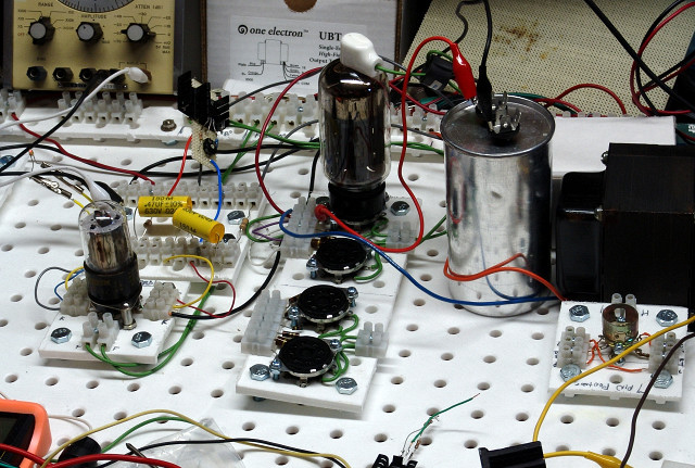 The amplifier on the Tubelab3 breadboard.
I tried tube current from 80 mA to 200 mA, and I tried several combinations of load impedances. The best results happen with a 4 ohm load on the 16 ohm tap on the transformer. That should work out to a 750 ohm load on the tube. The little UBT-3 transformer didn't like this too much, and I figure that I was loosing several watts in the OPT.
Power at the onset of clipping was 9.1 watts. The distortion is related to tube current. At 5 watts output I get 4.8% distortion with 80 mA of tube current. At 150 mA the distortion drops to 1.64% and at 200 mA the distortion is 1.09%. The output impedance is under 1 ohm, which is mostly OPT losses. The voltage drop on the primary was not nearly as severe as the secondary when switching from an 8 ohm load to a 4 ohm load.
I listened to it (in glorious mono) for most of the afternoon with both of my "8 OHM" speakers in parallel on the 16 ohm tap. The sound is awesome, solid bass, crystal clear highs....... I found that 80 mA sounded just as good at 200 mA except for some bass heavy music (Pink Floyd).
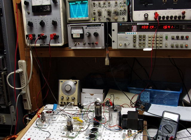 The amp under test.
Before anyone rushes out to build this, let me explain a few things.
The driver is pretty straight forward. The input tube is the high mu section of a 6EM7. Just about any tube with enough gain will work here. Adjust the load resistor and tube current to match your choice.
The second stage requires a tube that can operate linearly at low plate voltages, and not explode as the plate voltage swings up to the supply voltage. The sweep tubes made for vertical (frame) output duty work well here, so this is why I chose the 6EM7. A 6DR7 (9 pin) will work well also. The CCS load is the key to developing a lot of voltage swing. A choke load should work also, but good chokes are not cheap and the CCS chips are.
The output section requires some thought. I used a 6LW6 sweep tube because I know how much abuse they can take without issue. The screen grid rating is 275 volts, I ran it all day at 550 volts. The plate dissipation rating is 40 watts, I had it at 80 watts for about 2 hours, and up to 100 watts for brief testing. At 80 watts there is no hint of plate or screen grid glow. At 100 watts the plate gets a dull red glow after about 2 minutes. Consider the requirements if you choose a different tube. All 6LW6's are not created equal either, some are not capable of this abuse.
You need to choose a tube (or parallel combination) that can take this for extended time periods, you also need to plan the chassis for some heat dissipation.
Am I going to build one of these? Yes! First, I need to find a bigger OPT. Then, I plan to do some further testing. See those empty sockets, I plan to fill them up! I haven't decided which tubes yet, or just how much power it will make. I probably will settle for a reasonably powered SE cathode follower, but I plan to build an insanely powerful P-P cathode follower if all of my other circuitry works out.
I will do more testing on this circuit, and post updates as I find out anything useful.
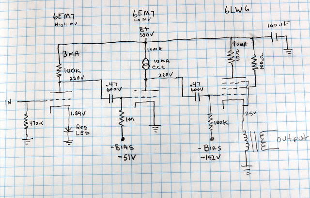 The Schematic.
First Update
Today I revisited the cathode follower test circuit. I could only get 9 watts out of that amp during testing even when I cranked the tube dissipation up to 100 watts. That just isn't right. I suspected my grossly mismatched output transformer, which turned out to be the correct assumption. I was seeing almost 400 volts peak to peak across the primary, but only 9 watts out. With almost 300 ohms of DCR, all my power was just heating up the transformer.
So in order to find out what OPT I need, I eliminate the transformer, and test the amp without it. My normal procedure is to replace the OPT with a choke, and a parafeed cap, without the OPT. I then place power resistors in place of the OPT and experiment with the value to find the optimum load for the amp. If everything is connected to bench power supplies, you can adjust the plate voltage, the tube current, and the load impedance until you get exactly what you want. Then replace the resistor with the same value OPT. No load lines necessary!
I dug out a 55 pound choke that I have been saving for my SE OTL amp. It is 2 Henries at 2 Amps, with a 6 ohm DC resistance. I tried several different loads, and found that a 500 ohm load resulted in 30 watts output with the tube on the edge of redness. That is more like it. I settled on 600 ohms for the best balance of power, distortion, and tube life. I can get over 20 watts with conservative tube current, and 28 watts with the tube at 80 watts of dissipation. Without the limitations of the OPT you can measure the amplifier circuitry itself. Frequency response is 20 Hz (limited by the choke) to 95 KHz. Distortion is 0.9% at 5 watts rising to 5% at 28 watts.
Knowing this, I reached for the first transformer that I thought would get me 600 ohms. It is a Plitron P-P toroid OPT rated at 400 watts. I am using it in parafeed configuration, without a cap. The DCR of the choke is so low that I only have 2 volts across it, so I don't need a cap. I still get 28 watts, so the old OPT was just not working.
I have been listening to it for most of the evening, and it sounds good, too good. The best transients of any amp that I have built. Spooky real! Now I am going to need to buy some good 600 ohm SE OPT's because I just have to build one. The toroids are destined for a big P-P amp, and the chokes are just too big.
Second Update
I bought two used 600 ohm "Eastern Audio" OPT's. I also laid out a PC board that followed the schematic above, except that the output tube was changed to a 6336A, or any of the usual regulator dual triodes.
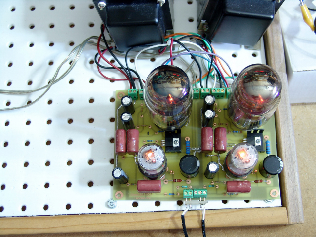 Here the new PC board is tested with the Eastern Audio transformers.
Third Update
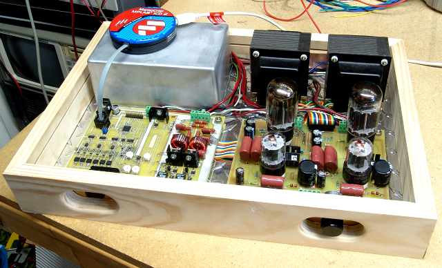
As I stated before, this amp design was a small piece in a big puzzle. The cathode follower amp is the PC board on the right. It is similar to the board shown above except the low voltage signals are routed through a ribbon cable to clean up the layout and fix a few pesky oscillations. The board on the left is the logic board. It controls the bias on all tubes, handles start up and shut down, has data logging features, and has a few other functions that will be revealed later. The silver box in the rear contains an analog power supply consisting of two toroidal transformers, and some diodes and caps. It will be replaced with an SMPS when I have time to finish it. The box was used to allow easy removal without the holes in the chassis.
This design is on two PC boards in order to fit the requirements of the design contest. This is fine for me to develop the software for all of the cool features that the amp is capable of. I plan to reduce the design to four simple PC boards that can each be used individually, or all together in several unique amplifier designs. Why would I do this?
Would you like your amp to be able to dump its operating history into your PC so that you can graph the condition of the tubes, or see how much output power you really use? OH, did I mention that this is a SET amplifier that puts out 25 WPC, and realizes a plate efficiency near 50%. The audio path is 100% tube (except for my usual CCS load on the driver) and the distortion is really low. Do I have your attention yet?
Please don't email me for more info yet. The numbers quoted above are real measured data on the amplifier shown below. I have not had the time to touch it since October, and I doubt that I will for the rest of the year. As soon as I have more info, I will post it here.